Furnace equipments products
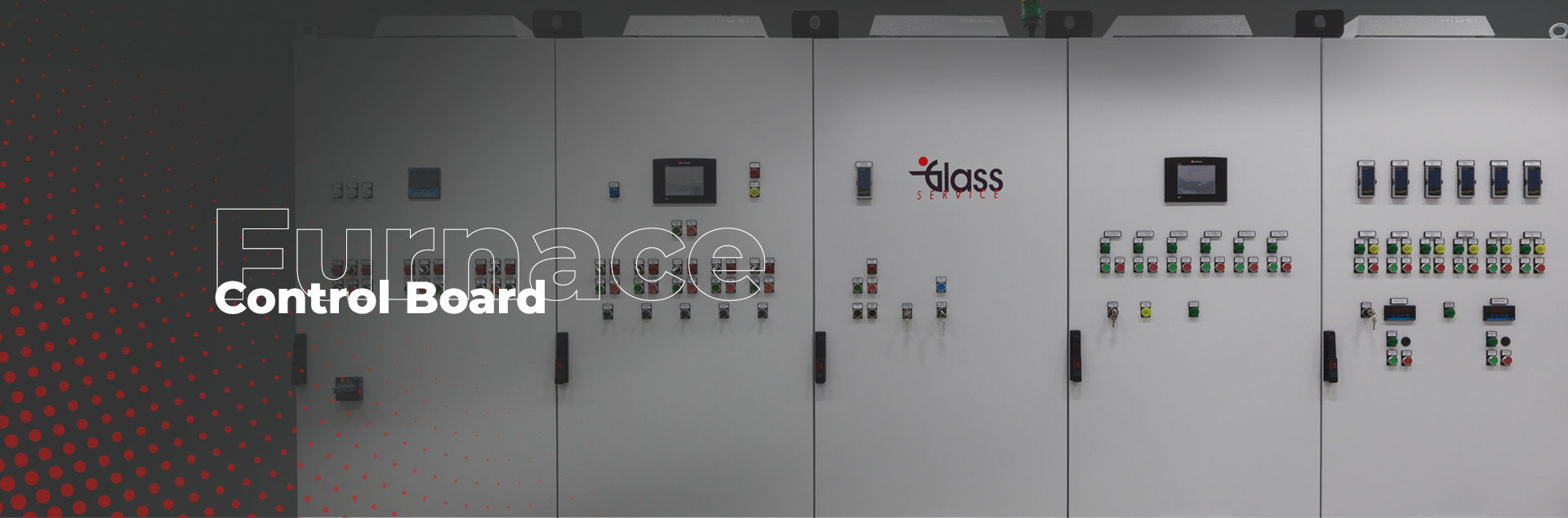
Furnace Control
Board
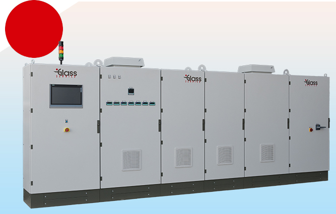
The new generation of control boards manufactured by Glass Service can solve all of the problems of furnace parameter management. The control boards are divided in 4 basic model with different electronic architecture but all based on the best modern control technology.
The reliability of the control boards is assured, based upon many years of experience, using only first class materials. The versions are described below using only Honeywell, Allen Bradley/Siemens and other first class component suppliers.
USEFUL LINKS
DOWNLOAD BROCHURE
Open System Information
All models of Glass Service control board use the “Open System Information” technology (O.S.I.). This technology allows, the use of the information not only
in the furnace control room but also in the local LAN using a Ethernet link. Information available on the LAN are reported in the single model description.
Control board CF2 are able to send information stored in memory to a Ethernet link, information can be send from recorder Sx series and also from the HC 900.
The main feature of this technology are:
1.
Web Server
With the recorder connected to a LAN, all process variables, alarm and message can be viewed from an internet browser with automatic refresh.
2.
Remote Viewer
Extends the user interface of the recorder onto the desktop PC. Providing full remote control of the unit launched from a web browser. Compatible with Micsoft™ Internet explorer 6 and higher.
3.
TrendServer Pro
TrendServer Pro is a fully network aware software package for real-time viewing and archiving of data with communications to the recorder. It supports all the capabilities of Trend managementr Pro plus real-time data acquisition and web browser access. TrendServer Pro provides secure multi-level, multi-user access to the recorder data by various departments with security. Standard features of TrendServer Pro include data archive tools, graphing, print import and export data facilities.
4.
TrendServer Pro
with OPC Server
Provides the same functions as the TrendServer Pro but includes the added function of an integrated OPC Server to allow easy interfacing to third party HMI software packages that support an OPC Client. This provides a real-time interface between servers and clients.
5.
E-mail server
Some events (alarms, totalizer, etc.) can be send by email to specific address from the recorder and also from the HC900.
6.
HC900
remote control
All variable in the DCS HC900 memory can be send by LAN to 3rd party device (PC or other) using Ethernet MODBUS standard or OPC standard. Also by a specific program “Hybrid controller” all the system status (LOOPS, Variable, alarms, etc.) can be read and check by LAN.
Glass Service Advantage
REDUNDANCY
All Glass Service control boards are based on a redundant architecture where all or the most important control features are redounded.
The redundancy are better reported in the single model description.
MODEL COMPARISON TABLE
The table below gives a brief comparison of the models
| Model | FC1 | FC2 | FC2 SCADA | FC2 - RD SCADA |
|---|---|---|---|---|
|
Control loops management |
Single loop UDC2500 Honeywell / P108 Eurotherm |
DCS HC900 CPU50
Honeywell |
HC900 CPU50
Honeywell |
HC900 CPU70
redundancy CPU |
|
Logic management |
PLC Siemens |
DCS HC900 CPU50
Honeywell |
HC900 CPU50
Honeywell |
HC900 CPU70
redundancy CPU |
|
Loops redundancy |
Not installed |
Single loop UDC2500 Honeywell / P108 Eurotherm |
HC900 CPU70 redundancy CPU / P108 Eurotherm |
|
|
Logic redundancy |
electromechanically |
HC900 CPU70 redundancy CPU / electromechanical |
||
|
Trend management |
Recorder multitrend
SX series Honeywell |
Recorder multitrend
SX series Honeywell |
PC SCADA CITEC |
PC SCADA CITEC |
|
Alarm interface |
Display touch screen ASEM |
Honeywell touch screen
operator interface |
PC SCADA CITEC |
PC SCADA CITEC |
|
Plant scada supervisor |
Not installed |
PC SCADA CITEC |
PC SCADA CITEC |
|

Model FC1
The model FC1 technology is reported in the following schematic diagram:
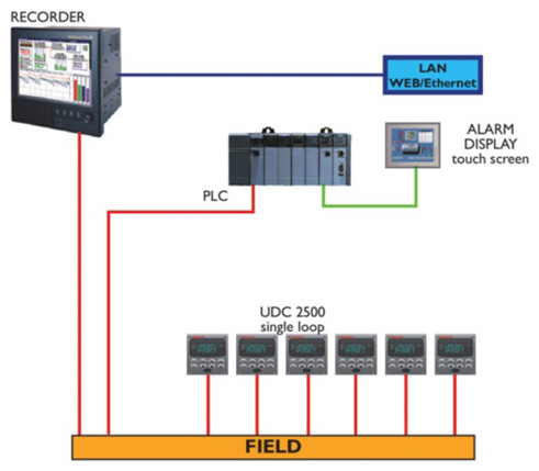
The technology is based on the Honeywell UDC 2500 single loop controller and the PLC model Siemens 1500 the main features of the board are reported in the following table.
| Model | FC1 |
|---|---|
|
Control loops management |
Single loop UDC2500
Honeywell |
|
Logic management |
PLC Siemens |
|
Logic redundancy |
Electromechanically |
|
Trend management |
On touch screen Recorder multitrend SX series Honeywell |
|
Trend recording |
On touch screen Recorder multitrend SX series Honeywell internal memory, exportable by flash card or USB memory key |
|
Alarm interface |
Display touch screen ASEM |
|
WEB link |
By Recorder multitrend SX series Honeywell |
|
Email server |
By Recorder multitrend SX series Honeywell |
|
WEB server |
By Recorder multitrend SX series Honeywell |
|
Remote viewer |
By Recorder multitrend SX series Honeywell |
|
Thermocouple health monitor |
By UDC 2500 Honeywell |
|
Totalize |
By Recorder multitrend SX series Honeywell |
|
Alarm monitor |
On touch screen Hitachi display |
|
Alarm history |
On touch screen Hitachi display |
Loops
The loops controlled by the board are:
- Temperature (input from thermocouple or pyrometer)
- Gas/air ratio
- Oil/air ratio
- Furnace pressure
- Combustion air temperature
- The loop installed and the single loop UDC2500 instruments installed depends on the specific application
Alarms
The alarms are displayed on the touch screen and recorded in the memory, the main allarm groups are:
- High/low temperature
- Device fault (fans – motor)
- Incorrect ratio Gas/air or oil/air
- Water cooling fault (es. For the batch charger)
Trends
The trends are reported on the Honeywell recorder SX series. Based on a 12.1” touch screen display. The trends are recorded in internal memory of 500 Mbyte and can be exported using a flash card or a USB memory key.
OSI* Technology available
The recorder SX series recorder is able open the information stored in memory to a Ethernet link. The main feature of this technology are:
- E-mail server – Some events (alarms, totalizer, etc.) can be send by email to specific address
- Web Server
- Remote Viewer
- TrendServer TrendServer Pro
Logic
The control board FC1 is able to manage the following in safety condition:
- Start/stop of the combustion fans
- Start/stop of the furnace cooling fan
- Gas valve management
- In case of oil firing, manage the oil heating and pumping unit
- Glass level and batch charger
Redundancy
In case of PLC fault the control board FC1 can be switched to emergency condition, all the main feature for the furnace heating are guarantee by an electromechanical emergency circuit.
Model FC2
The model FC2 technology is reported in the following schematic diagram:
The technology is based on the Honeywell DCS model HC900 controller single loop controller, the main features of the board are reported in the following table.
| Model | FC2 |
|---|---|
|
Control loops management |
DCS HC 900 CPU50 Honeywell |
|
Control loops redundancy |
P108 Eurotherm single loop |
|
Control loops operator interface |
Honeywell touch screen operator interface |
|
Logic management |
DCS HC 900 CPU50 Honeywell |
|
Logic redundancy |
Electromechanically |
|
Trend management |
On touch screen Recorder multitrend SX series Honeywell |
|
Trend recording |
On touch screen Recorder multitrend SX series Honeywell internal memory, exportable by flash card or USB memory key |
|
Alarm interface |
Honeywell touch screen operator interface |
|
WEB link |
1 Recorder multitrend SX series Honeywell
2 DCS HC 900 CPU50 Honeywell |
|
Email server |
1 Recorder multitrend SX series Honeywell 2 DCS HC 900 CPU50 Honeywell |
|
WEB server |
By Recorder multitrend SX series Honeywell |
|
Remote viewer |
1 Recorder multitrend SX series Honeywell 2 DCS HC 900 CPU50 Honeywell |
|
Thermocouple health monitor |
DCS HC 900 CPU50 Honeywell |
|
Totalize |
1 Recorder multitrend SX series Honeywell 2 DCS HC 900 CPU50 Honeywell |
|
Alarm monitor |
Honeywell touch screen operator interface |
|
Alarm history |
Honeywell touch screen operator interface |
Loops
The loops controlled by the board are:
- Temperature (input from thermocouple or pyrometer)
- Gas/air ratio
- Oil/air ratio
- Furnace pressure
- Combustion air temperature
- The loop installed and the single loop UDC2500 instruments installed depends on the specific application
Alarms
The alarms reported are displayed on the series control station and recorded in HC 900 memory for history, the mainly alarm groups are:
- High/low temperature
- Device fault (fans – motor)
- Incorrect ratio Gas/air or oil/air
- Communication LAN fault
- Thermocouple critical status (thermocouple health function)
- Furnace logic fault
- Glass level fault
- Water cooling fault (es. For the batch charger)
Trends
The trends reported on the Honeywell recorder SX series. Based on a 12.1” touch screen display. The trend are recorded in internal memory of 500 Mbyte and can be exported using a flash card or a USB memory key.
OSI* Technology available
The control board CF2 are able to send the information stored in memory to a Ethernet link, the information can be send from the SX series recorder and also from the HC900. The main feature of this technology are:
- Web Server
- Remote Viewer
- TrendServer Pro
- E-mail server
Logic
The control board by the DCS Honeywell HC900 is able to manage the furnace in safety condition as required by European standards:
- Start/stop of the combustion air fans Start/stop of the furnace cooling air fans
- Gas valve management according to the safety specification
- In case of oil firing, manage the oil heating and pumping unit
- Glass level and batch charger
- Energy consumption logging / totalising
All the logic parameter and variable are available on the LAN in several format (Ethernet modbus, OPC, etc) and can be send to several device (PC scada or 3rd party device).
Redundancy
In case of HC900 fault the control board FC2 can be shift in emergency condition, all the main feature for the furnace heating are guarantee by:
- Electromechanically emergency circuit for the furnace logic
- By the DC1030 single loop instruments for the loops.
A new features
HC900 remote control – All the variable in the DCS HC900 memory can be send by LAN to 3rd party device (PC or other) using Ethernet. MODBUS stand ard or OPC standard.
Also by a specific program “Hybrid controller” all the system status (LOOPS, Variable, alarms, etc.) can be read and check by LAN.
Model FC2 SCADA
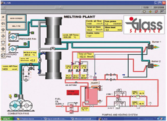
A typical schematic of the FC2 technology is shown below:

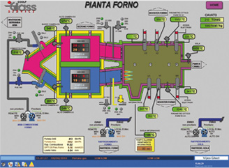
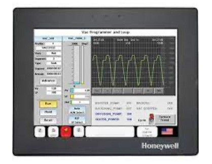
The operator interface based on SCADA CITEC program is very user friendly. Based on active object software all the furnace functions are displayed as icons on push buttons onthe screen.
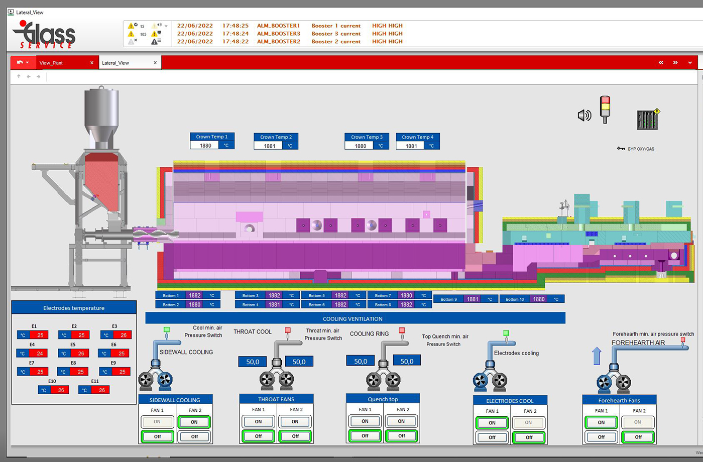
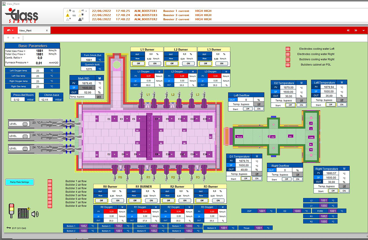
The furnace, distributor and forehearth zones are displayed in graphic display. Some examples of the screen as reported in the following description.
The technology is based on the Honeywell DCS model HC900 controller single loop controller, the main features of the board are reported in the following table.
| Model | FC2 - SCADA |
|---|---|
|
Control loops management |
DCS HC 900 CPU50 Honeywell |
|
Control loops redundancy |
P108 Eurotherm single loop instrument |
|
Control loops operator interface |
PC + SCADA CITEC software |
|
Logic management |
DCS HC 900 CPU50 Honeywell |
|
Logic redundancy |
Electromechanically |
|
Trend management |
1 On touch screen SX series Honeywell
2 PC + SCADA CITEC software |
|
Trend recording |
1 On touch screen SX series Honeywell internal memory, exportable by flash card or USB memory key |
|
Alarm interface |
PC + SCADA CITEC software |
|
WEB link |
1 – SX series Honeywell 2 – DCS HC 900 CPU50 Honeywell |
|
Email server |
1 – SX series Honeywell 2 – DCS HC 900 CPU50 Honeywell |
|
WEB server |
SCADA CITEC software |
|
Remote viewer |
1 – SX series Honeywell 2 – DCS HC 900 CPU50 Honeywell |
|
Thermocouple health monitor |
DCS HC 900 CPU50 Honeywell |
|
Totalize |
1 – Recorder multitrend SX series Honeywell 2 – DCS HC 900 CPU50 Honeywell |
|
Alarm monitor |
PC + SCADA CITEC software |
|
Alarm history |
PC + SCADA CITEC software |
Loops
The same features as the model FC2, but the operator interface used is PC + SCADA CITEC technology.
Alarms
The alarms reported are displayed on PC-SCADA CITEC operator interface and recorded in HC 900 memory for history, the main alarm groups are the same than model FC2.
Trends
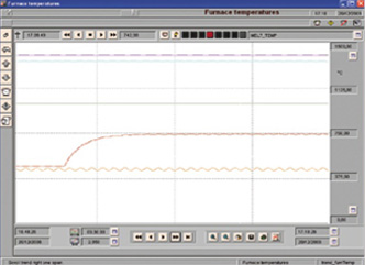
The trends reported on the Honeywell SX series recorder are shown on a 12.1” touch screen display. The trends are recorded in the internal memory of 500 Mbyte and can be exported using a flash card or a USB memory key. The trends are also reported in the SCADA software, a sample is shown below.
OSI* Technology available
The control board FC2 Scada are able to send the information stored in memory to a Ethernet link, the information can be send from recorder SX series and also from the HC900. The main feature of this:
Technology are:
- Web Server
- Remote Viewer
- TrendServer Pro
- E-mail server
- HC900 remote control – all the variables in the DCS HC900 memory can be send by LAN to 3rd party device(PC or other) using Ethernet MODBUS standard or OPC standard. Also by a specific program “Hybrid controller” all of the system status (LOOPS, Variable, alarms, etc.) can be read and checked by LAN.
Logic
The same features the model FC2, but the operator interface are used is PC + SCADA CITEC technology.
Redundancy
In case of a fault with the HC900, the control board FC2 can switch to emergency mode which allows manual control of all of the main features for the furnace operation by:
- Electromechanical emergency circuit for the furnace logic
- By the DC1030 single loop instrument for the loops

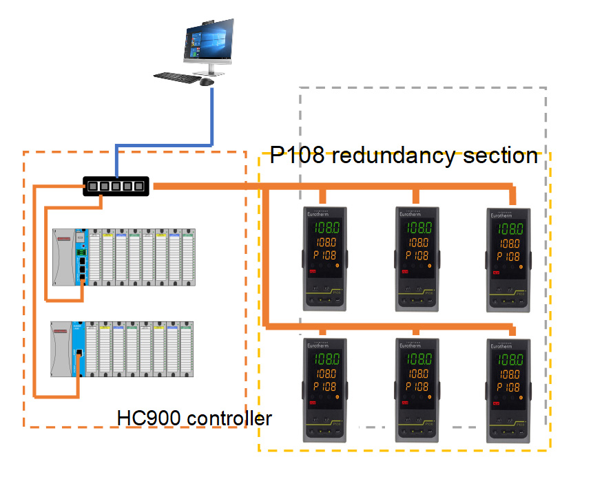
Model FC2 RD SCADA
The model FC2 – RD – SCADA technology is similar to the model FC2 – SCADA, but in this solution a very important difference is in the system redundancy. This model is suitable for continuous processes that cannot accept any production stoppages, such as the glass industry. A typical schematic of the FC2 – SCADA technology is shown below:
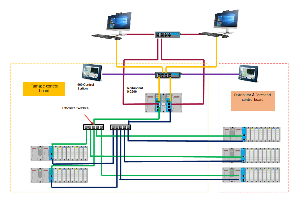
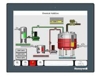
The operator interface based on SCADA CITEC program is very user friendly, based on active object software with all of the furnace function displayed as icons on push button on the screen. The furnace ,distributor and foreheaths are displayed on a graphic display. Some typical samples of the screen are shown in the following description. The PC SCADA CITEC in redundancy version is a full redundant program, all the information is mirrored on the N.2 PC server and can be switched automatically in the case of any failure of the other PC.
The technology is based on the redundancy Honeywell DCS model HC900 CPU70 controller the main features of the board are reported in the following table.
| Model | FC2 - RD SCADA |
|---|---|
|
Control loops management |
Redundancy DCS HC 900 CPU70 Honeywell |
|
Control loops redundancy |
Redundancy DCS HC 900 CPU70 Honeywell |
|
Control loops operator interface |
Redundancy PC + SCADA CITEC software |
|
Logic management |
Redundancy DCS HC 900 CPU70 Honeywell |
|
Logic redundancy |
1 Redundancy DCS HC 900 CPU70 Honeywell 2 Electromechanically |
|
Trend management |
1 On touch screen SX series Honeywell
2 PC + SCADA CITEC software |
|
Trend recording |
1 – On touch screen SX series Honeywell
internal memory, exportable by flash card or USB memory key 2 – Redundancy PC + SCADA CITEC software |
|
Alarm interface |
Redundancy PC + SCADA CITEC software |
|
WEB link |
1 – SX series Honeywell 2 – DCS HC 900 CPU70 Honeywell |
|
Email server |
1 – SX series Honeywell 2 – DCS HC 900 CPU70 Honeywell |
|
WEB server |
By Recorder multitrend SX series SCADA CITEC software |
|
Remote viewer |
1 – SX series Honeywell 2 – Redundancy DCS HC 900 CPU70 Honeywell |
|
Thermocouple health monitor |
Redundancy DCS HC 900 CPU70 Honeywell |
|
Totalize |
1 – SX series Honeywell 2 – Redundancy DCS HC 900 CPU70 Honeywell |
|
Alarm monitor |
Redundancy PC + SCADA CITEC software |
|
Alarm history |
Redundancy PC + SCADA CITEC software |
Loops
The loops controlled by the board are:
- Temperature (input from thermocouple or pyrometer)
- Gas/air ratio
- Oil/air ratio
- Furnace pressure
- Combustion air temperature
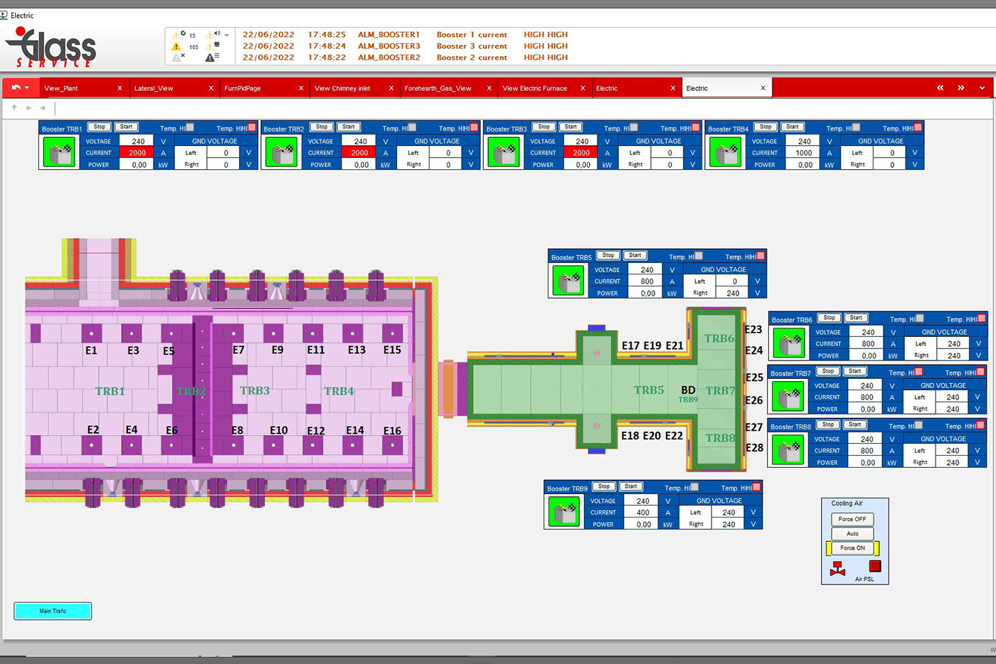
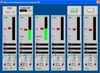
- The loops installed depends on the specific application. A typical graphic display is shown below.
Alarms
The alarms reported are displayed on a double PC+SCADA CITEC operator interface and recorded in HC 900 memory, the mainl alarm groups are:
- High/low temperature
- Device fault (fans – motor)
- Incorrect ratio Gas/air or oil/air
- Communication LAN fault
- Thermocouple critical status (thermocouple health function)
- Furnace logic fault
- Glass level fault
- Water cooling fault (es. For the batch charger)
Trends
The trends reported on the Honeywell SX series recorder are shown on a 12.1” touch screen display. The trend are recorded in internal memory of 500 Mbyte and can be exported using a flash card or a USB memory key. The trends are also reported in the redundant SCADA software. The information is recorded and mirrored in both PCs and in case of a fault with one PC the second will continue recording.
In the event that N.1 PC is off line intermittantly, at the first link access all of the logging information lost will be send from the active PC automatically. Using this technology both PCs are recording the logging data without any time hole. A display sample is shown below.
OSI* Technology available
The control board FC2 Scada are able to send the information stored in memory to an Ethernet link, the information can be send from SX series recorder and also from the HC900. The main feature of this technology are the same the FC1 model:
- Web Server
- Remote Viewer
- TrendServer Pro
- E-mail server
- HC900 remote control – All the variable in the DCS HC900 memory can be send by LAN to 3rd party device (PC or other) using Ethernet MODBUS standard or OPC standard. Also by a specific program “Hybrid controller” all the system status (LOOPS, Variable, alarms, etc.) can be read and check by LAN.
Logic
The control board by the DCS Honeywell HC900 is able to manage the furnace in safety condition as required by European standards:
- Start/stop of the combustion air fans
- Start/stop of the furnace cooling air fans
- Gas valve management according to the safety specification
- In case of oil firing, manage the oil heating and pumping unit
- Glass level and batch charger
- Energy consumption logging / totalising
All the logic parameter and variable are available on the LAN in several format (Ethernet modbus, OPC, etc) and can be send to several device (PC scada or 3rd party device).
Redundancy
In case of N.1 CPU fault as N.1 power supply fault the CPU N.2 or power supply N.2 will take over the process control automatically without any change to the process conditions in the field. The redundancy device of the CF2 – RD – SCADA are:
- HC900 CPU70
- HC900 CPU70 power supply
- HC900 I/O power supply
- Ethernet link to the operator interface PC SCADA
- Ethernet link to the remote I/O racks
In case of a fault with the HC900, the control board FC2 – RD – SCADA can switch to emergency mode which allows manual control of all of the main features for the furnace operation by:
- Electromechanically emergency circuit for the furnace logic
- By the auto/man station for the actuator’s loops