Furnace equipments products
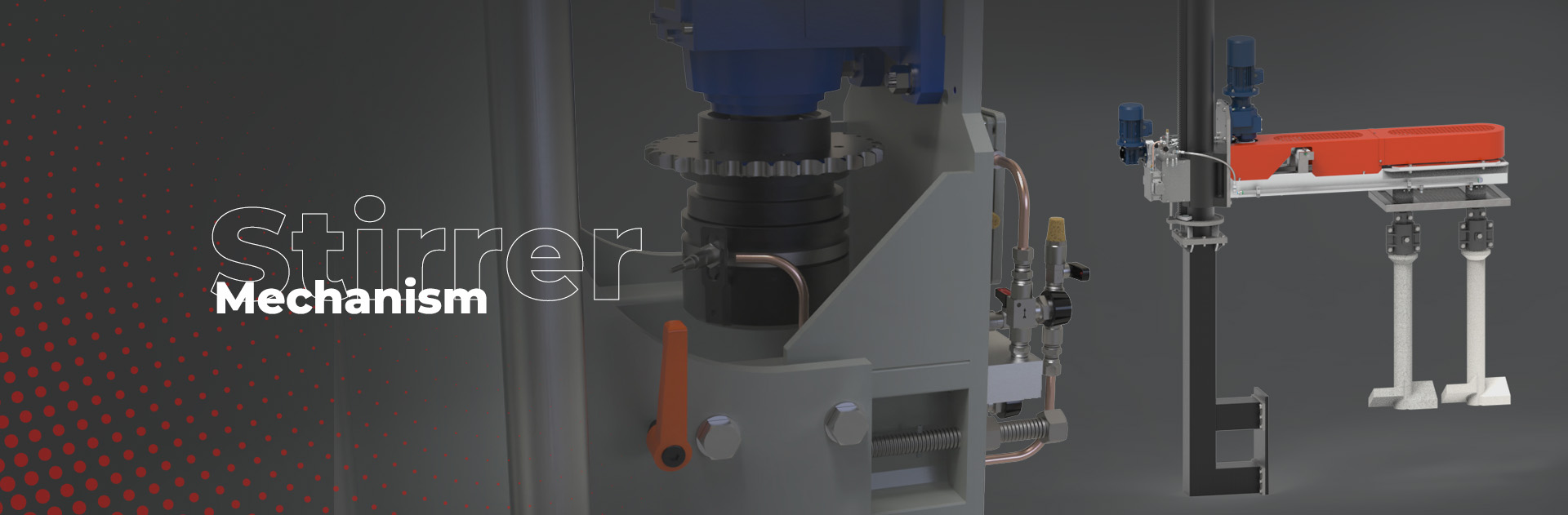
Stirrer Mechanism
The purpose of the Stirring Mechanisms is to homogenize the glass in the forehearth. The main applications are:
- Removal of cat scratches
- Removal of cords
- Glass blending in colouring forehearths
Taking into account the severe working conditions due to the high working temperatures, special attention has been paid to select the appropriate materials, both for the steel supporting frame and for the moving parts which are subject to wear, in order to improve their reliability and to reduce as much as possible the maintenance operations.
USEFUL LINKS
DOWNLOAD BROCHURE
Generally a stirrer mechanism comprises the following:
- A steel support frame
- A manual or automatic lifting system to remove the stirring unit
- Stirrers (paddle type or screw type)
- Control system (either a central control cabinet or a local control panel)
Glass Service produces the following stirrer systems:
- Standard flag-type stirring machine
- X-Y stirring machine
Flag-Type Stirrer Mechanism

- Strong steel structure
- Manual or motorized vertical movement
- Quick release coupling for the refractory screws or paddles
- Bearing lubrication and cooling system
- Up to 5 rotors can be installed
- Easy changing of the paddles/screws
- Easy maintenance
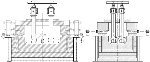
The stirring machine consist of:
- Steel vertical support column manufactured from large diameter steel tube
- Stirring mechanism that can be moved vertically on the above column by means of a manually operated rack and pinion system (optionally a motor can be installed)
- Drive system comprising an electric motor and gearbox with manual speed control
- Drive system with chain, tensioner and pinion
- Screw spindles provided with special high temperature graphite bearings
- Quick type coupling system for refractory screws or paddles
- Compressed air system with filter, pressure governor and accessories for bearing cooling and lubrication
- Heat shield
- Control box with drive inverter, emergency stop button and start/stop
Technical Characteristics
|
Vertical height |
Approx. 2.275 mm – customizable |
|
Vertical stroke of stirring mechanism |
Approx. 950 mm – customizable |
|
Distance from center forehearth to support column |
customized |
|
N° of rotors |
1 to 5 |
|
Max. weight stirrers |
120 kg each |
|
Stirrer revolution speed (manual adjustment) – screw type |
4.8 – 26 rpm |
|
Stirrer revolution speed (manual adjustment) – paddle type |
1.3 – 12,6 rpm |
|
Installed Power |
0.75 kW |
|
Power supply |
380 V 3 Ph – 50 Hz / 440V 60 Hz |
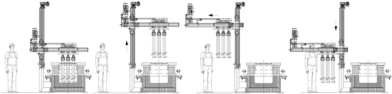
Maintenance and Replacement of Stirrers
The maintenance and the replacement of the paddles/screws is easily carried out. The operation sequence for this is as follows:
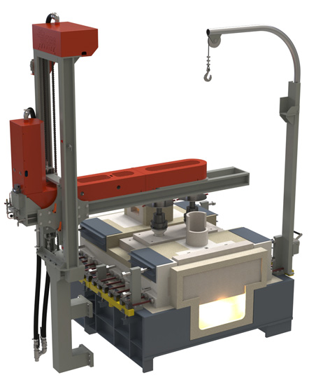
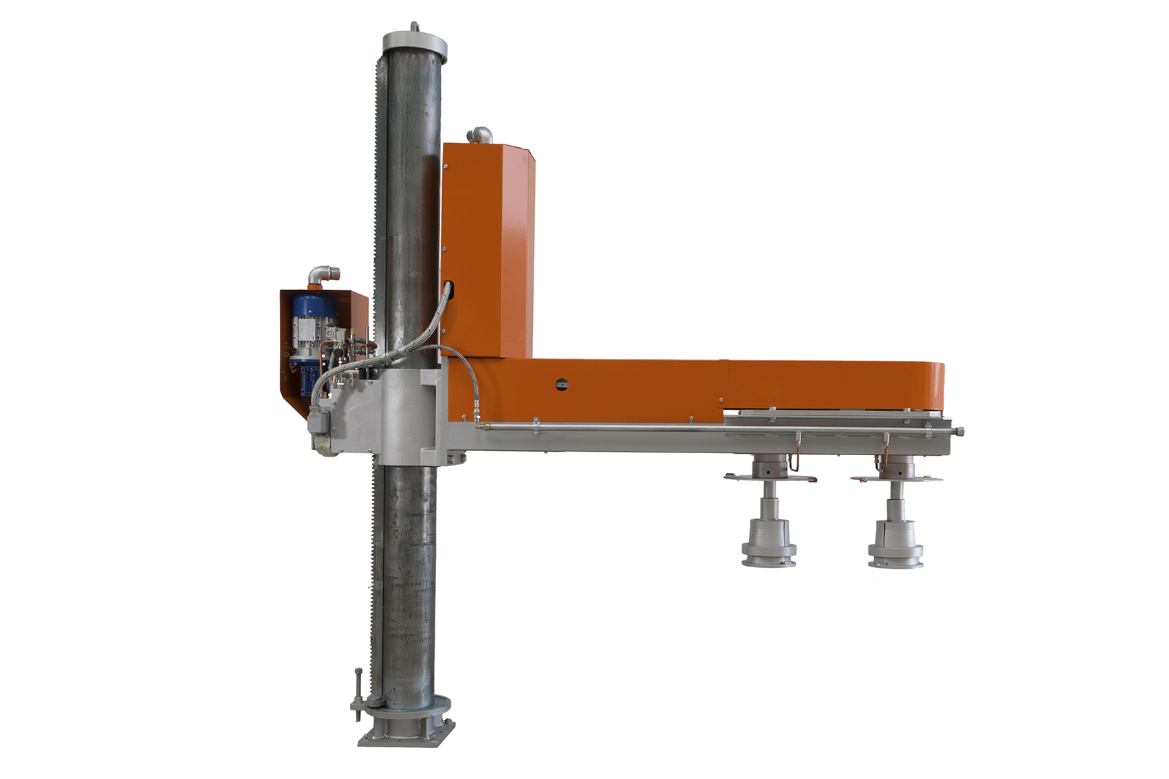
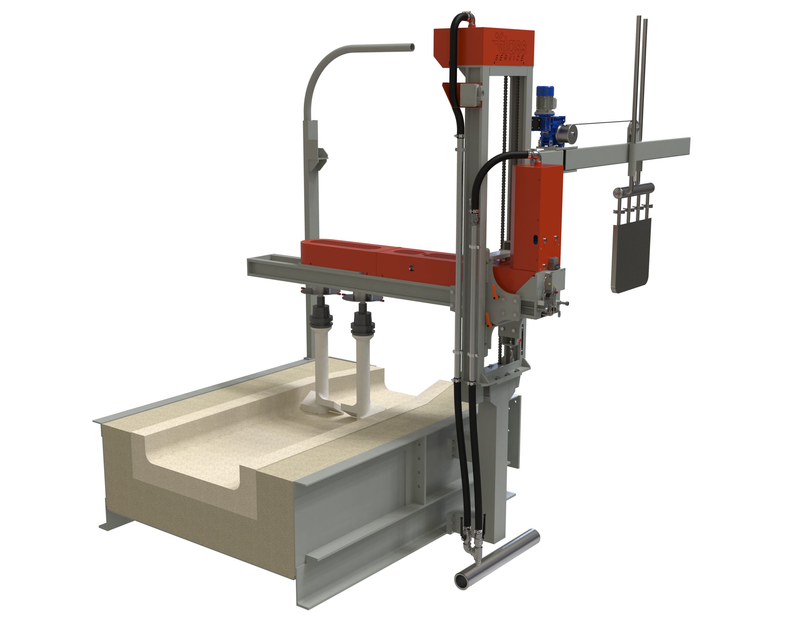
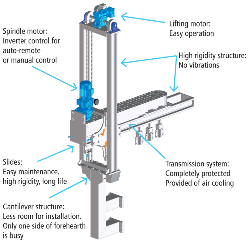
X-Y Stirrer Mechanism
Minimal installation spaces
Maintenance operation simplified
Quick type coupling system for refractory screws or paddles
Bearing cooled
and lubricated
Up to 5 rotors installable
Minimum space required for stirrer replacement
X-Y MOVEMENTS
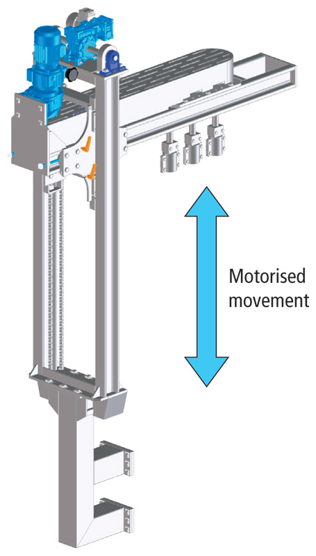
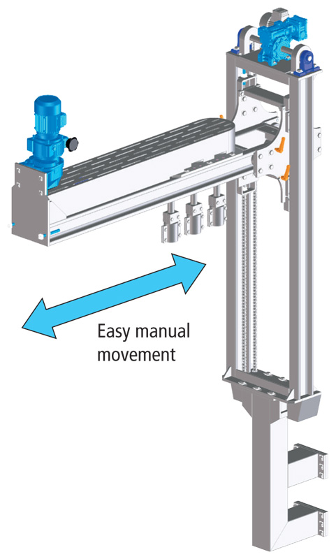
Glass Service has developed a stirring mechanism with two movements on both the X and Y axes that greatly reduces the space required for the installation and simplifies any maintenance operation. This machine is a vertical structure attached to the forehearth steel frame. An electric motor drives the chuck support arm up and down the structure.
This Y movement is achieved by moving the supporting arm on two parallel reinforced rails with special bearings and reinforced wheels. The motor and gearbox are located on top of the structure with a chain directly coupled to the chuck holder arm. In the unlikely event of chain breakage the arm cannot fall down due to the special design of the rails. The chuck support arm can easily slide towards the side of the forehearth on a horizontal arm. This movement is again operated on two parallel and reinforced rails with special bearings and reinforced wheels whilst power transmission is achieved through a rack and pinion. Each spindle turns on large graphite ball bearings. Thanks to this innovation the following features can be achieved:
- Minimum installation space
- Any maintenance operation, both on paddles or motor, is simpler and performed away from the hottest area of the forehearth
- The re-positioning of the spindles over the forehearth is very simple and precise.
Technical Characteristics
|
General dimensions |
According forehearth dimensions |
|
N° of rotors |
1 to 5 |
|
Rotors interaxis |
Tailored |
|
Max. weight of each stirrer |
60 kg |
|
Stirrer revolution speed (manual adjustment) – screw type |
4.8 – 26 rpm |
|
Stirrer revolution speed (manual adjustment) – paddle type |
1.3 – 12.6 rpm |
|
Installed power |
0.75 kW |
|
Installed power for spindle arm raising mechanism |
0.18 kW |
|
Power Supply |
Various |
ROTORS MOVEMENTS
On the top of the chuck holder arm the rotors power transmission group is located. Rotors are driven by a motor plus its gearbox, allowing a perfect control of the rotation speed.
This group is designed to allow, for each rotor, the possibility to rotate in two directions, so that, according to the installation the system can be configured as following:
- All rotors with the same rotation sense
- Each rotor rotating in opposite rotation
Optionally an inverter can be used to control the rotation speed. Each moving part of the machine is fitted with steel guards for safety purposes as well as to protect the mechanisms from dust. The drive assembly is also cooled and lubricated by means of compressed air.
The machine can support any type of rotor currently available on the market.
The chuck and rotor coupling system is a quick release model.
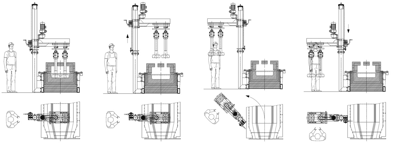
Maintenance and Replacement of Stirrers
The maintenance and replacement of the paddles/screws is easily carried out and requires very little space at the side of the forehearth. The operation sequence for this is as follows:
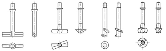
Rotors Type
Rotors type selection
Two types of rotors can be used, these are:
- Paddle type
- Screw type
Glass Service will suggest the correct type of rotor according to the customer requirements.
Below are some types of rotors that Glass Service can supply according to the requirements of the customer (and many others…):
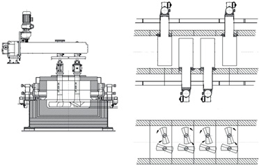
Rotors positioning
Depending on the forehearth width, type of glass, type of colouring, the available space at the sides of the forehearth etc., we will offer the best solution for the installation of the stirring unit.
Below are simple sketches of a possible installation:
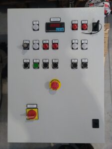
Control cabinet
Glass Service can provide a compact control cabinet including:
- Main power on/off
- Motor protection control
- Start / stop push buttons for spindle rotation
- Emergency stop button
- Red flashing light for alarms
As an option we can provide remote control cabinet with:
- Inverter control for spindles rotation
- Speed control device for chucks rotation (AUTO / MAN, INC/DEC speed, integrated display). A spindle speed control using an inverter integrated into the control cabinet will allow the system speed to be controlled remotely in the optimal range (i.e. 1.4 to 13 rpm for paddles) both from a remote DCS (with a 4-20 mA signal) as well as directly from the stirrer cabinet, setting a value between 0 and 100%.
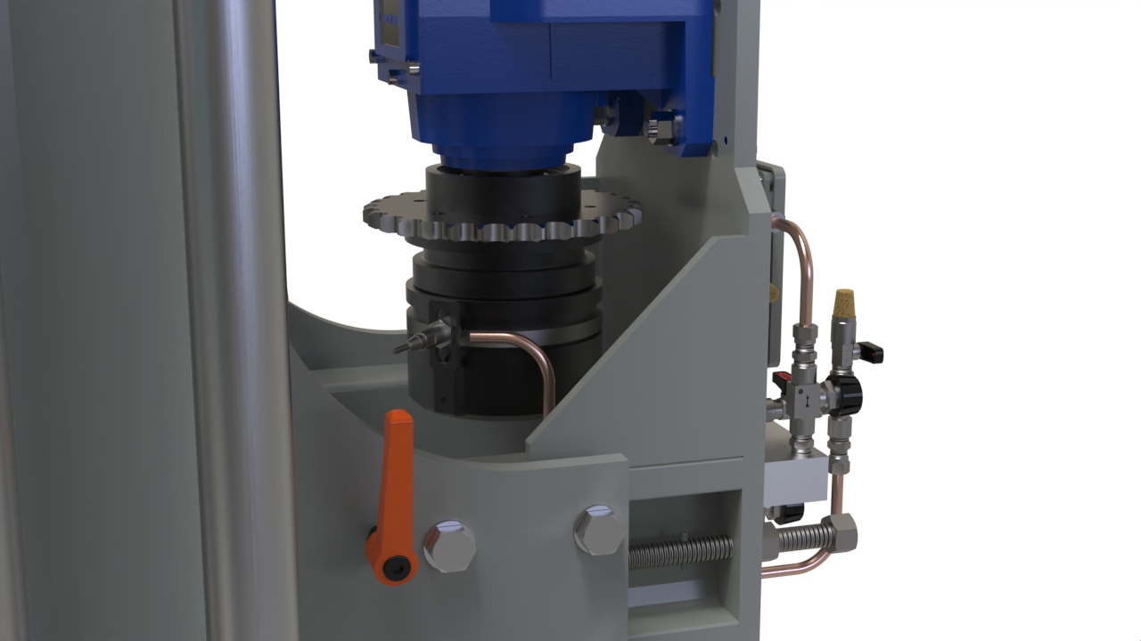
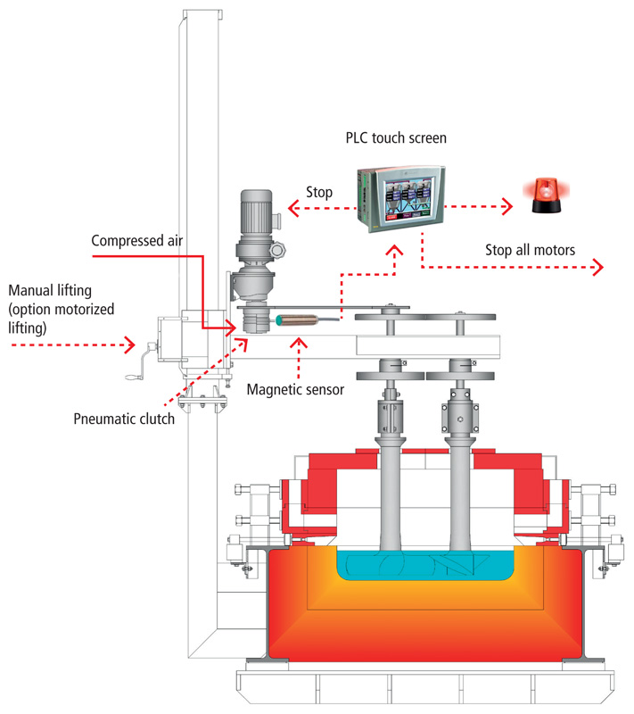
Options
- Pneumatic clutch available
- Motorized vertical lifting
There are some options that we can provide:
- Motorized vertical lifting: if required, the vertical lifting can be supported by an electric motor driven by up-down pushbuttons.
- Pneumatic clutch: to avoid that rotors can be broken by any extra torque on the same. The pneumatic clutch is very useful in case of colouring foreheart installations or in case of installations with several sets of propeller type stirrers. In the case of one refractory stirrers breaking, it can also break the neighbouring stirrer. The risk of several stirrers being damaged is real when many stirrers are installed. The pneumatic clutch can solve this problem. The clutch max torque is set by the operator during the start up. If a rotor suddenly requires extra torque the pneumatic clutch opens and stops the mechanical transmission, the opening is detected and the PLC stops all stirrer machine motors and sounds an alarm.
This video illustrates the operation and advantages of the stirrer mechanism produced by GLASS SERVICE SRL. Designed for use in forehearths, this system ensures effective mixing of molten glass, eliminating temperature and color variations.