Furnace equipments products
Booster
1.
Electric boosting has been used for many years in the glass industry, initially most boosters were installed simply to increase furnace output. Today electric boosting can be utilised to give a number of benefits including:
- Increased furnace output
- Improved and stable glass quality
- Improved efficiency of fossil fuel firing system
- Improved thermal gradients in the melter
- Reduced time for colour changes
- Increased furnace flexibility when changing furnace output (pull changes)
2.
Each booster system is tailor made according to the furnace type and the customers requirements. Glass Service has developed their boosting system technology and can offer systems as follows:
- Melting end booster to increase output
- Thermal barrier booster to stabilse convection currents
- Refining booster
- Throat booster for use during heat up and during low pull conditions
3.
Each booster system supply by Glass Service can be supplied as a stand alone system or integrated into the furnace control system. Glass Service can supply all of the equipment required for the electric booster including:
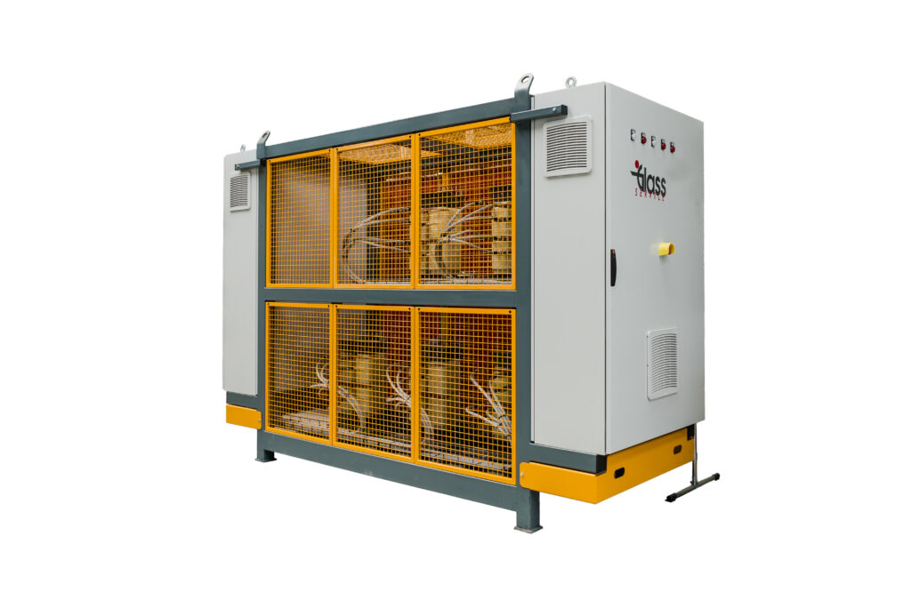
- Power transformer(s)
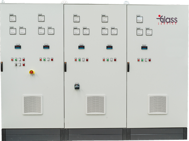
- Control panel
- Electrodes and holders
- Electrode holder water cooling system
- Emergency air cooling
- Cables and connectors
Melting Booster
Increasing furnaces output
Reducing emissions
Improve glass quality
Increase furnace output flexibility
Recommended for coloured glass (green, amber, etc.)
Retrofit installation possible in operating furnace
When installed to increase the furnace output, the booster can normally provide an additional 30% over and above the glass melted by the fossil fuel firing. Note that electric boosters are recommended in colour glass furnaces (green, amber, etc.) to maintain bottom temperature.
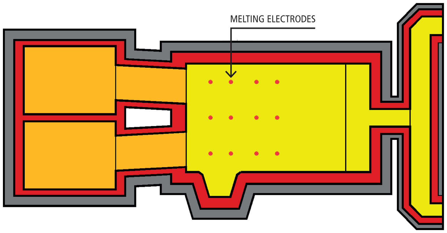
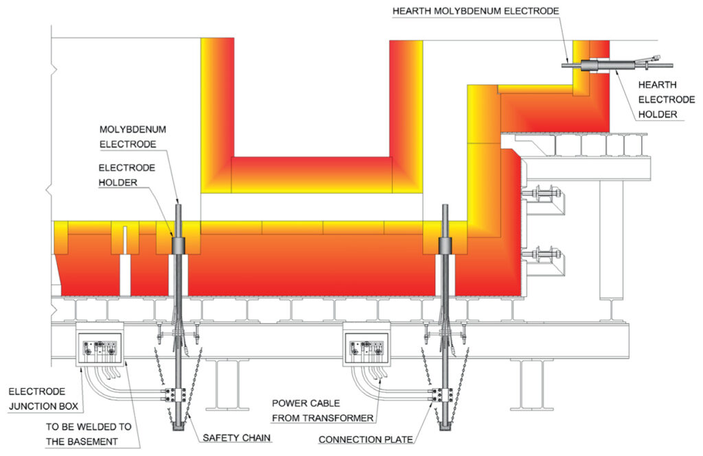
The melting booster electrodes can be installed in the furnace side walls or in the furnace bottom, however bottom electrodes are preferred to minimise corrosion of the side wall blocks.
The majority of boosters (depending upon furnace geometry), have an installed power in the range of 400 to 1200 kVA although much larger systems are not uncommon when the cost of electricity is attractive.
Transformer Technology
The power transformer technology used depends on the size of the installation. For smaller installations:
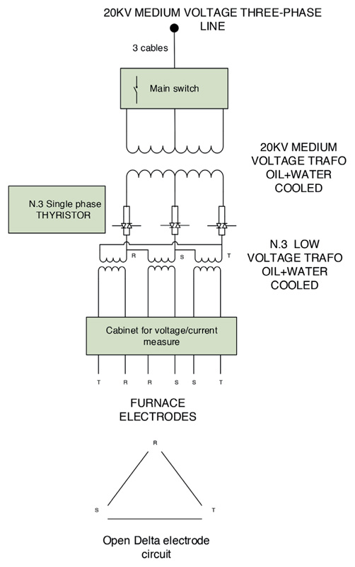
- Thyristor technology with dry transformer
For larger installations:
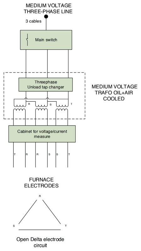
- High voltage, oil filled transformer with tap change switch
With the exception of throat boosters which are usually single phase, the majority of installations are three phase and are designed to give a balanced load on the three phases. Each system is individually designed to suit the customers requirements, the installed power of the booster being calculated to provide the required increase in output (or other parameter), taking into consideration the furnace design, glass composition / colour, furnace bottom temperatures, electrode current density, etc.

Thermal Barrier Booster
Increasing furnace output
Reducing emissions
Improve glass quality
Increase furnace output flexibility
Improve the convection current at the hot spot
Retrofit installation possible in operating furnace
Although the barrier booster provides additional energy which can increase output, the main purpose of this type of booster is to reinforce and fix the convection current in the furnace at the hot spot and to increase the temperature in the front zone of the furnace.
The improved convection current creates a barrier to the batch resulting in better batch cover and an increase in glass quality. It is recommended for soda lime glass and for deeper furnaces. The installed power can vary from 200 to 1000 kVA depending upon furnace size and geometry. The driver technology is usually thyristors &-dry-transformer. In some cases, for higher power the tap position changer can also be used. The connection is usually three phase and the electrodes are positioned to give a balanced load on all three phases.
The electrodes are molybdenum rods with water cooled electrode holders. The barrier booster power is limited by the furnace bottom temperature, glass temperature and electrode temperature.
Throat Booster
The throat booster is used for heating up of the furnace’s throat or temperature maintenance. It is recommended for deep refiner furnace, coloured and special glasses.
The power installed is usually in the range 30-70 kVA.
The driver technology is thyristor and dry-transformer low voltage drive single phase (e.g. 400 Vac).
The electrodes are molybdenum with water cooled electrode holders.

Circuit type on load
tap position changer transformer
- Clean sinusoidal wave output
- Long transformer life over 40 years
- High energy efficiency
- No obsolescence
The use on load tap changer transformer technology OLTC has been developed by Glass Service and is a very powerful and reliable transformer technology.
The OLTC is the most used technology in all the electrical power stations for voltage adjustment.
The voltage is regulated by step with no energy disconnection.
The OLTC transformers used by Glass Service have the following features:
- Voltage input, medium voltage, range from 4000 to 20000 Volt
- Power range 400-1200 kVA
- Three phase or mono phase available
- Voltage output regulator from 21 to 29 step
- Voltage output range from 80 to 300 Volt
- Transformer primary connection, delta, zigzag (interconnected star) for special unit
- Transformer secondary connection, open delta, close delta
- Special transformer SCOTT-TYPE also available
- Transformer cooling ONAN (oil-natural; air-natural) or ONWF (oil-natural; water-forced)
- Bucholz safety relay, oil temperature control, water temperature control
The OLTC transformer has several advantages:
- Clean sinusoidal wave on the output
- Strong construction
- On load tap position changer operating life over 40 years (1,2 million operation maintenance free)
- High energy efficiency (low losses)
- Reduced field cabling
- Long life and zero obsolescence, can be reused for several campaign
Circuit Type Thyristor Unit
The thyristor unit TU is used for low power boosters in the range of 30-400 kVA, this system is considerabily cheaper to instal than OLTC. The thyristor drive technology developed by Glass Service has increased energy savings and safety levels. The TU comprises a Thyristor unit control cabinet and one or more dry transformers. The power is regulated by phase angle control.
The TU develop from Glass Service has the following features:
- Voltage input range from 220 to 600 Vac
- Voltage output 80-300 Vac
- Power range from 20 to 600 kVA for each transformer
- Dry transformer with multi voltage selection on the secondary circuit are fitted with a temperature sensor connected to the safety control system in the control panel
- Continuous power regulation
- Connection open or closed delta or special connection
Control System
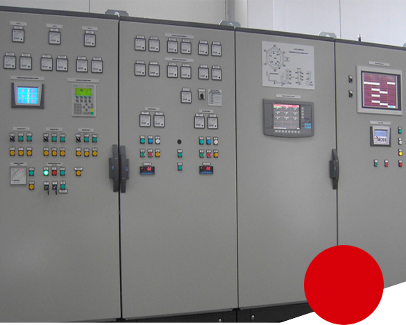
Glass Service has developed a special control system dedicated to booster technology. The system is based on DCS Honeywell HC900 and is able to manage the Tap position changer booster OLTC or the thyristor TU booster. Control system is able to manage:
- Power booster PID or current booster PID
- Voltage input
- Voltage output
- Current value for each electrodes
- Temperature value for each electrode
- Earth current and voltage
- Water cooling for each electrode
- Transformer alarms
- Thyristor alarm
- Emergency condition strategy manage
The HMI could dedicate by local touch screen panel or central PC SCADA. Al the process parameters and variables are controlled and recorded in the control system for process analysis.
Water Cooling
- Easy maintenance
- Visual flow water control
- High reliability
- Strong construction
- Easy water flow regulation and control
Each booster has a dedicated water cooling circuit to provide cooling water to the electrode holders using a special flow control and monitoring system designed by Glass Service.
The water flow is manually controlled and in the event of low water flow any increase in temperature is detected by a temperature sensor. In addition any pressure drop is detected by a pressure switch. The water flow switch is highly reliable and very simple to maintain.
Electrode Holders
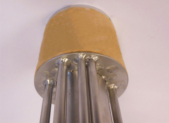
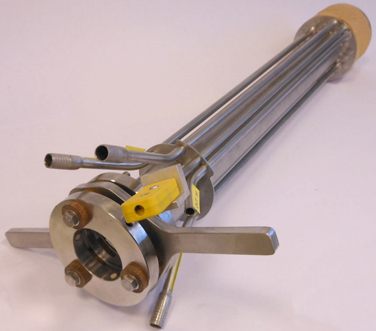
Strong mechanical construction, one piece head
Double cooling circuit water + air
Air cooling circuit for easy hot installation
Horizontal or vertical installation
Full accessories including supports, connectors, etc.
The electrode holder is manufactured from a special alloy with resistance to high temperatures. The head is produced from a single piece, machined and welded using laser technology.
Holders are supplied for use with a range of electrode diameters including 1.50, 2.0, 3.0 and 4.0 inch.
Main electrode holder features:
- Dual cooling circuit, water primary and emergency air
- Thermocouple K type for temperature head detection
- One block machined head
- Laser welding tube cooling connection
- Max head temperature 1000°C
- Operation head temperature max 800°C
- Cooling water consumption 5 l/min
- Max water temperature 35°C
- Cooling water pressure 2-4 bar
- Installation vertical or horizontal
The electrode holder can be equipped with several installation accessories:
- Cooling water special tube with high electrical resistance
- Electrode holder with mechanical support and electrical insulation
- Emergency support for bottom installation
- Water and air valve and fittings
